Topographical Survey 2D to 3D sketchup

Today I needed to take a 2D survey and create a landscape in Sketchup.

I had the elevation data in the autocad file but it was in metres (I work in mm) and was just text, it had no Z axis data.

Original Survey Points

So I needed to get AutoCAD to generate the Z data from the text. However the text was in metres, so first needed to convert it to mm.

Using the Find (and Replace) command I searched the text for the dot or fullstop between the two numbers e.g. 84.51 and replaced it with nothing. So the text became 8451.

All it needed now was the trailing zero. That was easier said than done! I tried several text replacement applications, one was freeware and was completely useless as it required registration and the demo was limited to a small number of items. Others refused to work and some seemed to only work on mtext. Eventually I found one that works a charm, thanks Tharwat!

So now I had a load of text and blocks without any other data. There are a couple of lisp routines I found to assist with adding the Z data. One extracts the data into a text file (I found that I could not manipulate that data as point cloud in AutoCAD so I dismissed it) and the other takes the insertion point of the text (slightly out from the actual survey point but suitable for my needs). They are pntconv.lsp and Txt2pnt.lsp respectively.

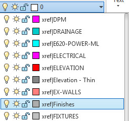
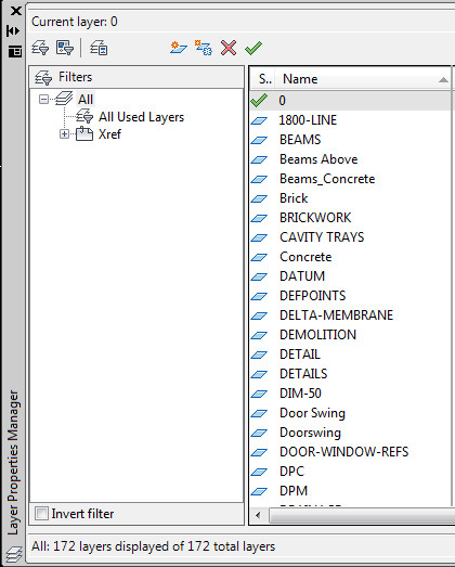
I used quickselect to remove all the blocks and was left only with the text.

Then I ran txt2pnt.lsp, and selected all the text, for some reason it did not like that and only create some points. So I ran the lisp several times selecting smaller groups and that worked.

Viewing the point cloud in 3D there were a few stray points that I removed. Also I removed the original text to create a “pure” point cloud.

Now I had a point cloud that I could bring into Sketchup.

Survey Point Cloud
Survey Point Cloud

For this you will need points_cloud_triangulation.rb and the other Ruby file delauney2.rb which the first needs. delauney2.rb is available from Sketchucation. However the file needs renaming to delaunay2.rb when placing into the plugins folder (but works).

Then import the drawing into Sketchup, select all the points (make sure they are exploded) and run the plugin points_cloud_triangulation.rb!

Voila a mesh that can now be smoothed, edited etc!

Sketchup Mesh
Sketchup Mesh


Text to Sketchup

Sketchup 7 (the last free Sketchup to have a DWG import option) doesn’t seem to have a way to bring text from AutoCAD in.

So when a flat topographic survey is brought in, the survey points are not labelled. Not very useful.

However if you have full AutoCAD with Express Tools, you can type TXTEXP to “explode” the text to polylines. Very useful!

Create Hatch

Bizarrely AutoCAD has not (as far as I am aware) created an easy hatch creation method, preferably in a GUI. This is long, long, long outstanding and should have been introduced back in R14 or earlier. If you want to create a hatch, you have to write it out by hand in a text file (there is no automation either), giving the text file a .pat extension.

Apart from the header row for the name and description of the hatch file, the hatch format is like this:

angle, x-origin,y-origin, delta-x,delta-y,dash-1,dash-2

Each line in the text file describes a drawn line, whether this is solid or dashed. All patterns are made from lines that are dashed or continuous and nothing else (a dot a line with a very short or no length). The dash length is variable so you then build up a hatch patten from a set of dashed lines that intersect. 

In order to create say herringbone brick you have the following pattern text:

0, 0,0, 10,10, 30,-10
90, 20,-30, -10,10, 30,-10

This creates a dashed line one way that intersects with one 90 degrees to it and when they repeat a brick pattern occurs. For such a simple shape it is still quite hard to wrap your head around the way they work!

If a complex hatch is required it is expected of the user to somehow translate their drawings from a set of lines into the hatch format. This is of course nigh-on impossible for most users and for a pattern with over one hundred entities will take forever to measure and write out the results, and the 7 step help file isn’t really that helpful and is quite vague.

This is one my major annoyances in AutoCAD that they fiddle with this and that and don’t fix fundamentally missing features like this!

——

If you are thinking, man I cannot do that, don’t worry if you have the full version of AutoCAD (sorry LT guys) you can install a LISP file to do this for you. The awesome guys at Cadalyst posted in one of their tips a hatch creation LISP.

This LISP has two functions, draw and save. Accessed through DRAWHATCH and SAVEHATCH (strangely enough).

The draw hatch command command creates a 1×1 box in drawing units, so for metric in my case this is a 1x1mm box. Tiny!

——

So this is the process I followed to create my hatch.

Firstly, draw your tessellating hatch inside a square, using only line entities. Make sure no curves are present. Then copy this in all directions to make sure the tessellation works! Save this drawing as your template for the hatch.

Secondly, scale your square down to a 1×1 unit square. You can save this as another file if you want. Leave this drawing open (save first, as always before doing anything major).

Thirdly create a new drawing and run DRAWHATCH. This will create a 1×1 unit square with nothing in it. Go back to your open drawing and copy the entities within the square (you can copy the square for ease and delete it after the copy if you want), and paste inside the square drawn in the new drawing by DRAWHATCH.

Fourthly, run SAVEHATCH and select the line objects (polylines won’t work so explode them first) and follow the prompts. A command line window will appear to make things easier.

Fifthly, give it a description and then save it as a file name in a place where you can load them into AutoCAD. Our practice as a server folder for custom hatches.

So that’s it you now have a hatch. One of the problems I encountered with this method is that the created hatch is very small. You will have to enter a large scale factor to correct this.

——

If you are feeling adventurous, you can load the pattern file into Excel and scale the numbers created up to suit. Save out as CSV to get the comma delimited text file back!

Delete Key

One of my colleagues mysteriously could not use the delete key in AutoCAD. It worked fine in other programmes.

Generally this is seems to be due to a crash that resets certain variables (for some strange reason).

In this case the PICKFIRST variable was reset to 0. When PICKFIRST is at 0 it only allows objects to be selected after the command is initiated. The delete key does not initiate the ERASE command so the nothing happens when the delete key is pressed and PICKFIRST is set to 0, appearing to be broken.

If you set PICKFIRST to 1 then objects can be selected and an command initiated after this selection. The delete key then works as you expect it to do.

Hatching, select or pick?

In the ribbon hatch system, the default method is to have pick objects, however there is a way to change this, or even to get the old hatch dialogue back if you like that (I have got used to the new hatch ribbon but some still like the old hatch dialogue!)

The system variable HPDLGMODE is the one to change this.

Set HPDLGMODE to 2.
This is the default behaviour of post 2010 AutoCAD. It uses the ribbon interface and pick point is default selection method.

Set HPDLGMODE to 1.
This brings back the old hatch dialogue box if you want it.

Set HPDLGMODE to 0.
This also uses the ribbon interface, however it uses the select objects as the default hatch selection method.

The setting out HPDLGMODE to 0 seems like a good option if you still use boundaries to create your hatch objects and whilst AutoCAD’s hatching system has definitely been refined it still can crash your session so this might be the best way forward until further refinements are made to the hatching system.

MTEXT Columns

I noticed today that a drawing I was working in had columns on by default in MTEXT. As there did not seem to be a way to turn this option off on the Ribbon and only an option to turn it off in the MTEXT editor once activated I had a root around for a setting (using the premise that AutoCAD has myriads of settings).

The setting to control MTEXT columns is strangely enough MTEXTCOLUMN. Set it to 0 to have no columns.

Block Scaling too Large

One of my colleagues reminded me of an age old problem I have encountered several times and never got to the bottom of, when inserting a block it scales to a strange size and doesn’t fit to the page.

This turns out to be yet another setting between the “American Imperial” measurement system and the “International ISO Metric” measurement that exists in AutoCAD.

It turns out that changing MEASUREMENT setting to 1 (metric), from the default of 0 (imperial) only changes the way hatches and linetypes scale and not the inherent way the drawing works. The underlying unit scale of the drawing is governed by other setting. So old drawings created when out-of-the-box AutoCAD defaulted to imperial might still have all the old settings.

DWGUNITS command line options

The option in question is DWGUNITS. It appears that the default is 1, which is inches. This is why a block drawn in a drawing using DWGUNITS of inches is inserted into a drawing set to mm scales to a differing scale!

As an aside DWGUNITS also sets linear display precision, which is also set by LUPREC.

The options after DWGUNITS is typed appear in a pop-up command line box for easier reading, they are as follows:

Unit for length:
This is the overriding base setting between metric an imperial, here we note that the original setting was 1 for the block template and we changed it to 3, which is the system we use in the office.

Linear display format:
This changes the output reading for items like DISTANCE from 2000.000(decimal) say to 2.000E+03 (scientific). I find the decimal easier to read so we will select 2 here.

Linear display precision:
This governs the number of decimal points in the output reading for items like DISTANCE. 0 gives a measurement of 2000, 1 results in 2000.0 etc. I tend to leave this at 3, but this is personal preference. (LUPREC system variable also changes this setting, and is also found in the dialogue box after typing UNITS, found under menu –> FORMAT –> UNITS).

Scale objects from other drawings upon insert:
This is the one that makes the drawings scale from one unit set to another. I have left this as YES as it will highlight any other blocks and drawings that might not have been set to mm in the first option. Otherwise the block will be inserted without scaling and the error persists.

Match INSUNITS to drawing units?
INSUNITS is another option to scale BLOCKS on insert. It is best to say yes here so they do match, otherwise errors could occur!

Scale objects in current drawing to reflect change in units?
This one you need to say no to. The reason being is that you have drawn a line that is 2000 units long, and in this case before changing the DWGUNITS this would have been interpreted as 2000 inches. AutoCAD can scale the drawing (which is sometimes useful when say changing from a drawing that was actually drawn in inches to metric) however in this case you want to preserve the “2000 units” as 2000 and just change the unit type from inches to mm.

Then the drawing and block drawn in the drawing will be compatible with other drawings drawn in mm.

Please note that DWGUNITS and UNITS are completely different commands.

Please also note the DWGUNITS command is undocumented in AutoCAD both 2013 and 2014 help, it might be present in previous versions but probably need to go back many years to obtain anything!

Dimension Tips

As always in AutoCAD there are numerous ways to do the same thing, mainly due to the way the program has matured over the years. Items that existed way back in R12 are still there in R19.1 (2014), even if they have been replaced with a “better” implementation. These legacy options can sometimes be useful and also if you are encountering a problem its likely that something has been drawn using an older method that in not compatible with newer options.

Dimension without any text added

Take for instance text suffices for dimensions. The usual way to append text is to either set it as default in the Dimension Style Editor or append it for an individual dimension using the properties box (see above).

However you can also append text using <> then whatever text in the Text Override box. This is useful as you can have this as well as a Prefix and a Suffix. The <> represents the dimension. For instance if I have a prefix of SO and a suffix of mm, I can use the following in the Text Override,

Overall <> opening

to achieve,

Overall SO 1045mm opening

This can be useful for one off dimensions where the text needs to be padded out to make the dimension clearer and the dimension style is carrying suffices that are required to be kept.

Dimension with text suffix option 2
Dimension with text suffix

The override box can also be used to place text below the dimension line whilst the dimension remains above. This is done using the <> X modifier! For example;

<> XTEXT

Dimension with text below the dimension line

Note that if you want the text to be centred no space is required between “X” and the text required otherwise a space precedes the text below the line.

The major drawback with using text override as the main method for applying suffices is that Match Properties will not carry the text override from one dimension to another, it has to be retyped, whereas a dimension with Suffix used will carry over.

Match Properties Settings

A quick post to highlight that AutoCAD has a lot a “hidden” settings that most people (including me) don’t use or even know about.

Take for instance Match Properties, this actually has a selective settings box so that only some of the properties from the source object are matched!

Match Properties Dialog Box

Note that when Match Properties is clicked and the source object is selected AutoCAD lists the current settings under “Current Active Settings”, usually this is everything, however you can type S (or click settings in 2013 and above) and you will be presented with the dialog to turn off (or on) various properties to copy.

XREFs and Layers

A colleague of mine was struggling with numerous issues when using XREFs. The two main ones where having multiple Layer States with XREF prefixes that couldn’t be removed and the other was not wanting to see the XREF layers.

Layer States Dialogue for no XREFs does not work with Ribbon pulldown

The first issue was frustrating as whilst there is an option to disable these is in the layer states manger dialogue, checking the box does not disable them in the Ribbon pulldown. Duh. So the solution ended up being, delete the layer states in the XREF.

The second issue was easy to solve as AutoCAD has this feature built-in and it works! It works with both the Layer Pulldown, Layer Palette and Classic Layer! Wow!

Layer Drop Down showing XREF layers

This is how to remove XREF layers from these palettes. You will need a filter (yup AutoCAD has layer filters!)

Layer Pallette indicating the filter section
Layer Palette indicating the filter section

On the panel on the left, click XREF, this will now show the list of layers for the XREF. Click on the checkbox below that states Invert Filter and voila, you have a list of layers without XREF layers within.