Random glitches, flat ucs and icon solid hatch

A colleague of mine could not hatch dots on a drawing at a higher density. I tried the usual regen and measurement commands to see if it was the hatch itself, however it was not to do with this.

After searching it could be a variable issue in the drawing but the drawing was from our standard template, but worth checking to see if HPMAXAREAS and HPMAXLINES were set to low values. They were not.

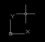
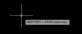
After further searching it became apparent that the drawing was a long way from the origin causing the glitches. This was apparent because the x leg of the UCS icon kept disappearing on zoom when in world UCS.

The glitches were:

  • Hatches not hatching properly at higher densities
  • ONSNAP not working properly
  • Fillet and trim not working properly

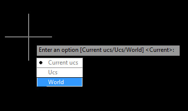
The solution was to create a drawing UCS closer to the drawing that fixed these glitches.

Hollow Dimensions

My colleague asks me today, “why are my dimensions hollow and not filled?” I thought, maybe FILLMODE is not set. But that was OK.

It turns out that this can be caused by non-flat or “elevated” drawings. I.e. 2D drawings that extend into 3D space. Usually caused by UCS not being rotated properly and it being skewed into 3D space.

The solution is to change the UCS in the modelspace or paperspace viewport so it is flat and things should be back to normal!

Macros – More Advanced

In my next post on customisation I will be looking at more advanced macro writing. After this post there will be a few individual macro examples which should be helpful!

Please refer to my macro basics and other customisation tutorials first.

In this tutorial I am going to refer to two UCS commands I have written to get around the lack of easy plan rotation in AutoCAD LT. In full AutoCAD you get a rotation box in the upper right corner that looks like the one below. This is unfortunately not available in LT.

Rotate from Viewcube

These are a bit more automated version of the tutorial I have posted before as I decided that even that was too much effort!

—–

The first macro rotates the UCS back to world and takes the plan view with it. This avoids the need for UCS follow being set to 1 and the annoying zoom extents bug it has.

^C^Cucs;w;plan;w;

So lets break down the macro above. Its just a simple chain of commands to do with the UCS and PLAN.

  • The first ^C^C at the beginning is escape twice to ensure that the command line is clear
  • Then the UCS command is started
  • Then the UCS command is told to reset to (W)orld
  • Then the PLAN command is started
  • Then the PLAN command is told to reset to (W)orld

Now the drawing is viewed in world view and the UCS is orientated the same way.

——

The second macro rotates the UCS to an object and then updates the view to suit.

^C^Cucs;ob \plan;c;

So lets break this one down as it has something slightly different in its layout.

  • The first ^C^C at the beginning is escape twice to ensure that the command line is clear
  • Then the UCS command is started
  • Then the UCS command is told to select by object
  • Then the script waits for input by the use of a space then a backslash
  • Then the PLAN command is started (after input)
  • Then the PLAN command is told to update to the (C)urrent

——

This formula can be used to make further buttons to emulate the plan rotate found in full AutoCAD or make any chain of commands work.

A quick way to create a macro is to run a command and follow the command line and write down your inputs and once you have completed the command you have the basics for putting together a macro.

—–

Lets make a macro to rotate the UCS and PLAN to the right. Here is a copy of the command line and below that is a list of the command inputs and then the resultant macro.

Command line:

Command: UCS
Current ucs name:  *NO NAME*
Specify origin of UCS or [Face/NAmed/OBject/Previous/View/World/X/Y/Z/ZAxis] <World>: z
Specify rotation angle about Z axis <90.00>: 90
Command: PLAN
Enter an option [Current ucs/Ucs/World] <Current>: c
Regenerating model.

Command input only:

ucs
z
90
plan
c

Macro:

^C^Cucs;z;90;plan;c;

Skewed World UCS

One of my colleagues had a drawing where the UCS had been rotated to suit a particular part of the drawing, however on setting the UCS back to World the World UCS was also rotated. AutoCAD helpfully shows the cursor as skewed if the UCS icon is not visible or obvious.

RotatedUCS
The UCS icon when rotated
RotatedWorldUCS
The World UCS rotated

This is due to the Plan view not being updated to suit the World UCS and is the exactly the same problem as noted in my UCS World post. Just type PLAN and select World to get back to normal. You can always tell if you are in World view by the UCS icon having a little sqaure on it. Any other view will just show the two axes.

WorldUCS
The World UCS as seen normally

As this is now really an LT problem as the full version of AutoCAD has a nifty rotate view button I have written a couple of scripts to set the UCS to an object and then rotate both the Plan and UCS to suit that object and also a useful one to get back to a World view. These will be published shortly as part of my customising AutoCAD series.


UCS World

I received a set of drawings today from a colleague, whilst this is not unusual, the drawings all had differing UCS settings, which was unusual, most of my colleagues do not touch the UCS.

Usually I reset the UCS to world and carry on. I like my modelspace to to be set to world so when I copy and paste the rotation stays the same to the screen. I tend to then rotate the UCS in viewports as and when required.

This time, typing UCS, W to reset to world UCS left me with this, a wonky UCS.

Wonky UCS
Wonky UCS

The UCS is wonky, or Y is not up the page. The square in the UCS indicates it is set to WORLD, so I was confused.

The problem was not that the view was set to the UCS but the UCS was (kind of) set to the view. I will explain. (See bottom of post for a quick explanation).

If you type VIEWTWIST, it should be set to 0 for the UCS to be the way I wanted it. I found it was set to 270!

wonkyucs02

Now I have run into another problem, the VIEWTWIST variable is readonly!

So lastly I found that typing PLAN and setting to WORLD reset everything to how I wanted.

wonkyucs03

Interestingly this problem seems to be similar to the one a while back with rotating the view in AutoCAD LT.

—-

For a quick method of the above, if the UCS is not in the default position and it is set to world, then the view has been rotated. To rotate the view back, type PLAN, then WORLD. Or click on the arrows above viewcube in full AutoCAD.

Rotate from Viewcube

Rotating LT

One of my colleagues asked this morning how to easily rotate the view (and UCS) to help with drawing, now in full version of AutoCAD this is simplicity itself.

Rotate from Viewcube

Just click on the arrows above the Viewcube to rotate the view and UCS simultaneously.

In AutoCAD LT this is more difficult, you can either use one of several command line methods, either using PLAN or UCS by object etc.

OR, this method seems to be easier (though it needs a little setting up). And here is how to do this.

Firstly, AutoCAD (LT) 2013 seems to come “out-of-the-box” with certain Panels turned off in the Ribbon. One of which is the UCS coordinate panel (why would they do this?) on View Tab.

Turn on coordinates panel.

Click on the View Tab and then right click anywhere on the panels below, then go to Show Panels, Coordinates. Now you have the coordinates panel which should have been there in the first place.

Secondly you need to make sure the view rotates with the UCS when you change the UCS. To do this click on the little arrow to bottom right of the Coordinates Panel, this brings up the UCS options box, Click “Update view to Plan when UCS is changed.” Click OK!

Enable Plan to Rotate with UCS

Now we are ready to go! (Phew!)

Rotate about the Z axis

Click on the drop down menu which has Axes and a rotate arrow. Click on the Z icon and voila you can now rotate around the Z axis and the drawing will follow. The default selection is 90 degrees so hitting enter after clicking will rotate by 90 degrees.

So now its “one click and enter” to rotate the view and UCS in AutoCAD LT versus the “one click” in full version, hopefully a simpler method than all the command line options!