Excel to AutoCAD layers

I have been attempting to update our office’s layer system. This would be difficult to do in AutoCAD without resorting to LISP or some programming to insert layers on mass. Creating lots of text on mass is really easy to do in Excel so that would be the program of choice to do this task.

The problem then comes of getting these layers into AutoCAD? There are numerous Lisp programs around on the internet to do this but what if you have AutoCAD LT only (as it lacks programming APIs)?

You can use Excels powerful cell commands to convert your layer list to a format that will then be able to create a script file. Below I will go through the steps you need to do to get this to work. (Note this is not my concept but I cannot find the original page where this was proposed).

Firstly create a blank Excel document.

Then place “-LAYER” in the 4th column over.

Now we are ready to input some data into the first three columns. This is in the order, layer name, colour, linetype. Make sure the second column for colour is text only to avoid any true colours being converted into numbers.

One completed we will now enter the following command below the cell with -layer in.

=IF(ISNUMBER(SEARCH(“,”,B2)),”N “& CHAR(34)&TRIM(A2)& CHAR(34)&” C T “&TRIM(B2)&” “& CHAR(34)&TRIM(A2)& CHAR(34)&” LT “&TRIM(C2)&” “& CHAR(34)&TRIM(A2)& CHAR(34),”N “& CHAR(34)&TRIM(A2)& CHAR(34)&” C “&TRIM(B2)&” “& CHAR(34)&TRIM(A2)& CHAR(34)&” LT “&TRIM(C2)&” “& CHAR(34)&TRIM(A2)& CHAR(34))

This creates the magic that is script. (Note the quotes are required for layer names with spaces).

Add layer information down the left and drag the little square in the bottom right of the excel cell to copy this to all cells below.

Once completed, save this file for future reference.

Copy the entire column of D and paste to a new file using paste values only.

Now the file is ready to become a script. Save as Formatted Text (space delimited) PRN file.

You should now have a text file that has the entire script for making your layers you need in it. Two steps to go!

Firstly we are going to rename the extension on the file (if you cannot see extensions follow this). This needs to be renamed from myscript.prn to myscript.scr.

Then open the file and add a return at the very end to create another line. This will terminate the last command and thus end the script.

Finally we load the script into AutoCAD using the command “script“.

Voila, all the layers are now in AutoCAD.
Xerox Printers AutoCAD Transparency Update

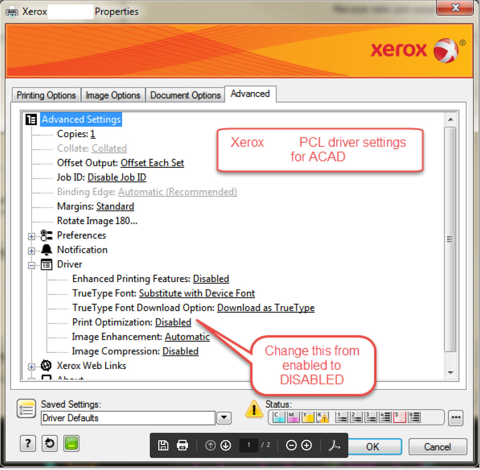
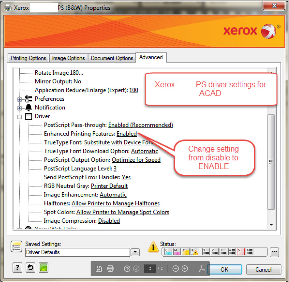
Recently we had Xerox printers installed and we could not get the transparancy to play nice with the printer, printing a small strip up the side of the page. We have now found a solution to the problem and after installing PS drivers and changing the settings on the driver page under the PC3 we use to the settings noted below all works fine. Thank you to placidrefining for their solution, which can be found on the following page. Whilst they note that this works with a 7970 printer, we have found that it works with our model as well.


I have posted the images below from that post here for reference.

xerox_transparency_working_pcl_settings

xerox_transparency_working_ps_settings-png


Hatch ribbon slow to load

So the hatch ribbon is slow to load? I found that the addition of custom hatches on a network path was the cause of the issue. Remove the network related path from the support files and the hatch command speeds up considerably. This seems to be a similar problem to that of the MTEXT problem I have encountered previously.

AutoCAD Broken File Associations

We upgraded AutoCAD LT 2015 to AutoCAD 2017 in the office by installing 2017, then carrying across settings and uninstalling the old one. On the first few PCs this worked OK but then it broke the Explorer file assciations horribly.

It produced an error along the lines of Cannot find AutoCAD LT 2015. Which was of course obvious because it was no longer on the machine.

After searching for the answer, this thread suggested wiping the machines, which currently was not an option.

The next option was to re-associate the files with AutoCAD rather than DWG launcher. This is really annoying solution as everytime you double click in explorer it launches a completely new process of AutoCAD which is very resource heavy when launched lots of times. This however was our temporary fix.

After some research, here is the solution if file associations in Explorer for AutoCAD are broken. This a tweaked version of what is shown on this page.

Fire up regedit (note you can break things with regedit, you have been warned!)

  1. Press WINDOWS-R on the keyboard to bring up the Run window, enter REGEDIT and click OK.
  2. Navigate to the following folder:
    HKEY_CURRENT_USER\Software\Autodesk\DwgCommon\shellex\apps
  3. Select the sub-key folder under “apps,” including the long string of numbers and letters that identify your version of AutoCAD.
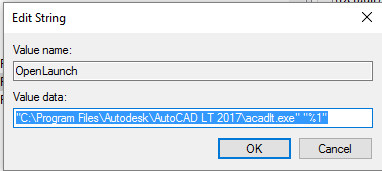
  4. On the right pane, verify that the “OpenLaunch” key contains the path to the correct acad.exe file. Double-click and edit if necessary – this bit you need to change 2015 to 2017.

    aclt-fileassoc03

  5. On the left pane, right-click the folder with the long string of numbers and choose “Copy Key Name.”
  6. Select the “apps” folder, and in the right pane, double-click (Default).
  7. Delete the current data value and paste the key name that you copied. Be sure to remove the folder path that precedes the key name.
  8. Click OK and close the Registry Editor window.

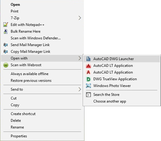
I found at this stage nothing seemed to have changed. So ensure that you right click and go to choose another app.

aclt-fileassoc01

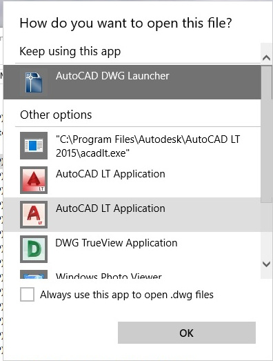
Once on the choose another app bit click on AutoCAD DWG Launcher and click Always use the app.

aclt-fileassoc02

This should mean that now when you double click DWG files AutoCAD LT 2017 will launch and all will work properly. You might find as we did that AutoCAD LT 2017 went through the initial start-up and migration settings again. Click always associate DWG files with AutoCAD LT if this box comes up.

You might find at this stage that your icons are still blank. No worries. Reboot.

Once rebooted we found when we double clicked that the “How do you want to open this file” box came up again. We clicked AutoCAD DWG Launcher and all the icons suddenly appeared.

Hope this fix works for you!

Polyline doesn’t plot its lineweight

Today a colleague of mine could not plot a polyline at the desired lineweight. We tried different layer with the colour changed to see if was the plot style interferring. Tried turning off scale lineweights. Tried overriding the lineweight on the object itself.  Tried a new plot style.

After all these attempts it occured to me that the polyline thickness might have a impact on the lineweights and it does.

Altering the polyline global width to 0 meant the lineweight now plotted correctly.

Plot transparency and Xerox printers

We had new printers in today, they were Xerox machines. They are quiet neat but not particularly useful when printing from AutoCAD. The reason why? Because for some reason AutoCAD and the Xerox drivers do not play nice with each other when printing with transparency.

When printing with transparency checked in the plot dialog the Xerox printers just print a small section of the page, about a 5th. Without that checked all is good.

The reason seems that AutoCAD prints vectors normally but when transparency is checked is prints rastors. For some reason this does not play well with the Xerox.

On this post on the second page are some settings but they are not on my driver version. I will investigate some options and update if I find a solution with the newer drivers.

Nested XREFs and layer states

If you use a system of drawing sheet and drawing model in your practice where both are seperate files and the sheets are like a piece of paper with the drawing information pulled into it then this is something you might have come across already, if not then this might help you in the future if you encounter it.

So generally you will attach one or two external drawings to a sheet file and then adjust layers to suit in the sheet file. However occaisonally you will set up a drawing with an XREF, usually an overlay type of drawing (not to be confused with overlay type of XREF) where you have a base drawing and the layers are adjusted to be simplistic and then further information is drawn over the top, e.g. a fire drawing or drainage drawing.

Xref_layerinfoattached

This is where it gets complicated. There is now a chain of drawings. Drawing A (the base drawing) –> Drawing B (the overlay type of drawing) –> Drawing C (the plot drawing). [Note: the arrows indicate XREF attachements]. This chain of XREFs is called nesting.

The problem comes when you want Drawing C to look the same as drawing B does. When you attach Drawing B to C all the layers on drawing A change to when they were first attached to drawing B, all the changes in drawing B seem to be lost. But when you go back to drawing B it still looks as it should. Confused?

The problem is AutoCAD pulls in XREFs (external references) from their source files and not through the nesting. So any information for drawing A setup in drawing B will not be imported into C as drawing C as the information is directly pulled from drawing A.

Xref_nestedlayerinfoattached

In order to circumvent this annoying behaviour layer states export and load should be used. Or you just reset them up if its only a few changes, but if lots of colour changes and layer adjustments have been made then this is the method for you.

This is taken from this page: (Copyright AutoDesk).

To export layer settings

  1. At the command prompt, enter LAYER.
  2. In the Layer Properties Manager, click Layer States Manager.
  3. In the Layer States Manager, create a new layer state or select an existing one. Click Export.
  4. In the Export Layer State dialog box, enter a file name and specify a location for the file.
  5. Click Save.
  6. Click OK to close each dialog box.

To restore layer settings

  1. At the command prompt, enter Layer on the command line.
  2. In the Layer Properties Manager, click Layer States Manager.
  3. In the Layer States Manager, select a named layer state.
  4. Select the settings that you want to restore.
  5. Click Restore.
  6. Click OK

Now you should have the correct layer information in drawing C!

Zoom extents ucs follow

Autodesk, oh Autodesk. Why do you not bother to fix major bugs? There are two zoom extents bug associated with UCSFOLLOW. One is one hatching and the other is when double clicking in the viewport. Whilst the viewport one can be controlled by locking the viewport, the hatching one can only be solved by turning off the UCSFOLLOW command. Which is silly really.

Grip edits not working

Introduced quite a while back for polylines and a while back for hatch, these allow you to add, edit and stretch existing lines by editing the blue square grips.

Gripedit01

However sometimes on polylines the edit menu for removing does not appear. This is usually due to two overlapping grips being present in the same space.

Gripedit02

To solve this problem, move the grip between the two points that don’t work to reveal the hidden overlapping grips. Now you should be able edit the grips again.

Gripedit03