MTEXT Slow to Start

If you have decided to place all AutoCAD items in a central location and link each machine across the network to those locations by adding them to the “Support File Search Path” then this is for you!

I was experiencing really slow mtext editing, slow loading of options dialog and slow loading of the hatch editor. I did some digging and found very few solutions. Only one that caught my eye where the response was “Maybe that’s part of the problem. ” I thought, lets test that. I removed the network paths from the support path and voila! Everything is blisteringly fast again.

Next step, work out why the network bit is slow!

Flickering LT 2014 solved

There seems to be two working solutions to AutoCAD LT 2014 flickering. One is to use a file from a previous version and the other which is far simpler to install is to use a registry patch.

Windows Registry Editor Version 5.00 [HKEY_LOCAL_MACHINE\SOFTWARE\Autodesk\AutoCAD LT\R20\ACADLT-D001\Variables\AECPSDAUTOATTACH] @=”0″ “StorageType”=dword:00000003 “SecondaryType”=dword:00000001 “LowerBound”=dword:00000000 “UpperBound”=dword:00000001 “PrimaryType”=dword:0000138b

Copy and paste the above into a text file. Rename it to autocadlt2014regpatch.reg (named only for ease of finding, the .reg is the important bit) and double click to install on affected machines. I have found that whilst this file can be stored in a server folder for ease of access, installing from the server is not possible and Windows 7 throws out an error. Just copy to desktop and install each time.


No layers information

One of my colleagues noted that they no longer could see the layers information in the Layers Drop down box when selecting objects.

autocad_pickfirstoff

The image above shows this issue, the object is on a differing layer to that shown, the Layers Drop down only shows the current layer.

In order to fix this the system variable PICKFIRST needs to be set to 1, which should be the default for this variable. Sometimes if AutoCAD crashes this seems to be reset to 0. Now when the object is selected it should display the layer information in the Layers Drop down.

autocad_pickfirston

No Thumbnails

One of my colleagues was struggling with files that did not have thumbnails. According to this (very helpful) post this is due to the THUMBSAVE setting not being set to 1.

This is a setting that is saved globally per machine but affects drawings. This can be confusing as there are global settings and drawing specific settings. Drawings saved on a machine with this off won’t create a thumbnail in the file.

Fields of Polylines

I regularly need to obtain areas for floor plans in the projects I work on. I have always drawn a polyline and then looked at the properties palette and knocked off 6 decimal places to get the result. Then this is written down on a non-printing layer.

I was thinking, there has to be an easier way, especially one that updates the area when the design changes.

Well there is! Fields. To access this click on the insert tab and click on field. Or type FIELD.

Fields01

Once you click this button you will be presented with a large box with a list of fields that can be used within it.

fields02

Scroll down to object, in the second column there is a small button to select the object in question. Select your polyline. The box will now update to the properties of that object, here you can select “area” and the result will display in the last column.

fields04

Now you can click OK to place the field object wherever you would like it! Or you can alter the precision, or in my case I wanted the result in square metres and not square mm which is the default.

In order to change format or add suffices etc. click on Additional Format. Now you get another box wher you can alter the way the field is displayed.

fields03

I used a conversion factor to produce the square metre information required.

And that is it! You now have a value that alters when you change the polyline size. If it doesn’t update, try REGEN or click on update fields in the Data section of the Insert tab.

Topographical Survey 2D to 3D sketchup

Today I needed to take a 2D survey and create a landscape in Sketchup.

I had the elevation data in the autocad file but it was in metres (I work in mm) and was just text, it had no Z axis data.

Original Survey Points

So I needed to get AutoCAD to generate the Z data from the text. However the text was in metres, so first needed to convert it to mm.

Using the Find (and Replace) command I searched the text for the dot or fullstop between the two numbers e.g. 84.51 and replaced it with nothing. So the text became 8451.

All it needed now was the trailing zero. That was easier said than done! I tried several text replacement applications, one was freeware and was completely useless as it required registration and the demo was limited to a small number of items. Others refused to work and some seemed to only work on mtext. Eventually I found one that works a charm, thanks Tharwat!

So now I had a load of text and blocks without any other data. There are a couple of lisp routines I found to assist with adding the Z data. One extracts the data into a text file (I found that I could not manipulate that data as point cloud in AutoCAD so I dismissed it) and the other takes the insertion point of the text (slightly out from the actual survey point but suitable for my needs). They are pntconv.lsp and Txt2pnt.lsp respectively.

I used quickselect to remove all the blocks and was left only with the text.

Then I ran txt2pnt.lsp, and selected all the text, for some reason it did not like that and only create some points. So I ran the lisp several times selecting smaller groups and that worked.

Viewing the point cloud in 3D there were a few stray points that I removed. Also I removed the original text to create a “pure” point cloud.

Now I had a point cloud that I could bring into Sketchup.

Survey Point Cloud
Survey Point Cloud

For this you will need points_cloud_triangulation.rb and the other Ruby file delauney2.rb which the first needs. delauney2.rb is available from Sketchucation. However the file needs renaming to delaunay2.rb when placing into the plugins folder (but works).

Then import the drawing into Sketchup, select all the points (make sure they are exploded) and run the plugin points_cloud_triangulation.rb!

Voila a mesh that can now be smoothed, edited etc!

Sketchup Mesh
Sketchup Mesh


Create Hatch

Bizarrely AutoCAD has not (as far as I am aware) created an easy hatch creation method, preferably in a GUI. This is long, long, long outstanding and should have been introduced back in R14 or earlier. If you want to create a hatch, you have to write it out by hand in a text file (there is no automation either), giving the text file a .pat extension.

Apart from the header row for the name and description of the hatch file, the hatch format is like this:

angle, x-origin,y-origin, delta-x,delta-y,dash-1,dash-2

Each line in the text file describes a drawn line, whether this is solid or dashed. All patterns are made from lines that are dashed or continuous and nothing else (a dot a line with a very short or no length). The dash length is variable so you then build up a hatch patten from a set of dashed lines that intersect. 

In order to create say herringbone brick you have the following pattern text:

0, 0,0, 10,10, 30,-10
90, 20,-30, -10,10, 30,-10

This creates a dashed line one way that intersects with one 90 degrees to it and when they repeat a brick pattern occurs. For such a simple shape it is still quite hard to wrap your head around the way they work!

If a complex hatch is required it is expected of the user to somehow translate their drawings from a set of lines into the hatch format. This is of course nigh-on impossible for most users and for a pattern with over one hundred entities will take forever to measure and write out the results, and the 7 step help file isn’t really that helpful and is quite vague.

This is one my major annoyances in AutoCAD that they fiddle with this and that and don’t fix fundamentally missing features like this!

——

If you are thinking, man I cannot do that, don’t worry if you have the full version of AutoCAD (sorry LT guys) you can install a LISP file to do this for you. The awesome guys at Cadalyst posted in one of their tips a hatch creation LISP.

This LISP has two functions, draw and save. Accessed through DRAWHATCH and SAVEHATCH (strangely enough).

The draw hatch command command creates a 1×1 box in drawing units, so for metric in my case this is a 1x1mm box. Tiny!

——

So this is the process I followed to create my hatch.

Firstly, draw your tessellating hatch inside a square, using only line entities. Make sure no curves are present. Then copy this in all directions to make sure the tessellation works! Save this drawing as your template for the hatch.

Secondly, scale your square down to a 1×1 unit square. You can save this as another file if you want. Leave this drawing open (save first, as always before doing anything major).

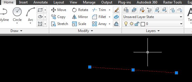
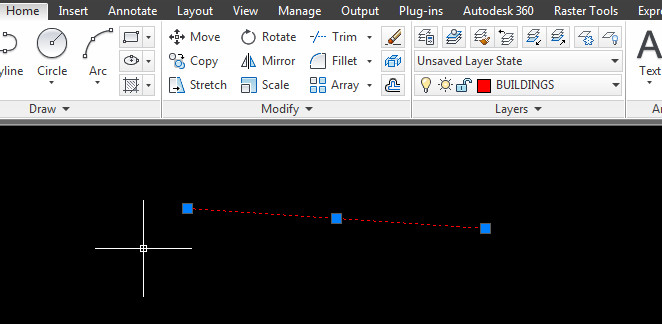
Thirdly create a new drawing and run DRAWHATCH. This will create a 1×1 unit square with nothing in it. Go back to your open drawing and copy the entities within the square (you can copy the square for ease and delete it after the copy if you want), and paste inside the square drawn in the new drawing by DRAWHATCH.

Fourthly, run SAVEHATCH and select the line objects (polylines won’t work so explode them first) and follow the prompts. A command line window will appear to make things easier.

Fifthly, give it a description and then save it as a file name in a place where you can load them into AutoCAD. Our practice as a server folder for custom hatches.

So that’s it you now have a hatch. One of the problems I encountered with this method is that the created hatch is very small. You will have to enter a large scale factor to correct this.

——

If you are feeling adventurous, you can load the pattern file into Excel and scale the numbers created up to suit. Save out as CSV to get the comma delimited text file back!

Delete Key

One of my colleagues mysteriously could not use the delete key in AutoCAD. It worked fine in other programmes.

Generally this is seems to be due to a crash that resets certain variables (for some strange reason).

In this case the PICKFIRST variable was reset to 0. When PICKFIRST is at 0 it only allows objects to be selected after the command is initiated. The delete key does not initiate the ERASE command so the nothing happens when the delete key is pressed and PICKFIRST is set to 0, appearing to be broken.

If you set PICKFIRST to 1 then objects can be selected and an command initiated after this selection. The delete key then works as you expect it to do.

Hatching, select or pick?

In the ribbon hatch system, the default method is to have pick objects, however there is a way to change this, or even to get the old hatch dialogue back if you like that (I have got used to the new hatch ribbon but some still like the old hatch dialogue!)

The system variable HPDLGMODE is the one to change this.

Set HPDLGMODE to 2.
This is the default behaviour of post 2010 AutoCAD. It uses the ribbon interface and pick point is default selection method.

Set HPDLGMODE to 1.
This brings back the old hatch dialogue box if you want it.

Set HPDLGMODE to 0.
This also uses the ribbon interface, however it uses the select objects as the default hatch selection method.

The setting out HPDLGMODE to 0 seems like a good option if you still use boundaries to create your hatch objects and whilst AutoCAD’s hatching system has definitely been refined it still can crash your session so this might be the best way forward until further refinements are made to the hatching system.