
Block Scaling too Large

One of my colleagues reminded me of an age old problem I have encountered several times and never got to the bottom of, when inserting a block it scales to a strange size and doesn’t fit to the page.

This turns out to be yet another setting between the “American Imperial” measurement system and the “International ISO Metric” measurement that exists in AutoCAD.

It turns out that changing MEASUREMENT setting to 1 (metric), from the default of 0 (imperial) only changes the way hatches and linetypes scale and not the inherent way the drawing works. The underlying unit scale of the drawing is governed by other setting. So old drawings created when out-of-the-box AutoCAD defaulted to imperial might still have all the old settings.

DWGUNITS command line options

The option in question is DWGUNITS. It appears that the default is 1, which is inches. This is why a block drawn in a drawing using DWGUNITS of inches is inserted into a drawing set to mm scales to a differing scale!

As an aside DWGUNITS also sets linear display precision, which is also set by LUPREC.

The options after DWGUNITS is typed appear in a pop-up command line box for easier reading, they are as follows:

Unit for length:
This is the overriding base setting between metric an imperial, here we note that the original setting was 1 for the block template and we changed it to 3, which is the system we use in the office.

Linear display format:
This changes the output reading for items like DISTANCE from 2000.000(decimal) say to 2.000E+03 (scientific). I find the decimal easier to read so we will select 2 here.

Linear display precision:
This governs the number of decimal points in the output reading for items like DISTANCE. 0 gives a measurement of 2000, 1 results in 2000.0 etc. I tend to leave this at 3, but this is personal preference. (LUPREC system variable also changes this setting, and is also found in the dialogue box after typing UNITS, found under menu –> FORMAT –> UNITS).

Scale objects from other drawings upon insert:
This is the one that makes the drawings scale from one unit set to another. I have left this as YES as it will highlight any other blocks and drawings that might not have been set to mm in the first option. Otherwise the block will be inserted without scaling and the error persists.

Match INSUNITS to drawing units?
INSUNITS is another option to scale BLOCKS on insert. It is best to say yes here so they do match, otherwise errors could occur!

Scale objects in current drawing to reflect change in units?
This one you need to say no to. The reason being is that you have drawn a line that is 2000 units long, and in this case before changing the DWGUNITS this would have been interpreted as 2000 inches. AutoCAD can scale the drawing (which is sometimes useful when say changing from a drawing that was actually drawn in inches to metric) however in this case you want to preserve the “2000 units” as 2000 and just change the unit type from inches to mm.

Then the drawing and block drawn in the drawing will be compatible with other drawings drawn in mm.

Please note that DWGUNITS and UNITS are completely different commands.

Please also note the DWGUNITS command is undocumented in AutoCAD both 2013 and 2014 help, it might be present in previous versions but probably need to go back many years to obtain anything!

Match Properties Settings

A quick post to highlight that AutoCAD has a lot a “hidden” settings that most people (including me) don’t use or even know about.

Take for instance Match Properties, this actually has a selective settings box so that only some of the properties from the source object are matched!

Match Properties Dialog Box

Note that when Match Properties is clicked and the source object is selected AutoCAD lists the current settings under “Current Active Settings”, usually this is everything, however you can type S (or click settings in 2013 and above) and you will be presented with the dialog to turn off (or on) various properties to copy.

Flickering Update Again

Further to my previous post regarding renaming AecCore.crx, it has been suggested that this could break other things. A slightly “better” patch would be to copy the AecCore.crx from the 2013 install and place it into the 2014 folder. This does work and no visible breakage yet!

Our CAD support people have suggested that this patch is a reasonable temporary solution though they say if an update from AutoDesk arrives then you will need to revert back to the 2014 version of the AecCore.crx file before installing the update.

Also the CAD support people looking at this flickering issue with AutoDesk at the moment and I will let you know the outcome of that.

Another flickering update

It appears that changing AecCore.crx in C:Program FilesAutodeskAutoCAD LT 2014 to AecCore.crx.old or similar (in order to stop it working) fixes the flickering symptoms, making the program usable again. However this will most likely break something else as this file is an object enabler. The underlying issue appears to be with the new mapping feature (which makes sense as there is a greyed out map pin next to unrecognised when the bar flickers) and that is not working properly.

We all wait now for a Service Pack or Hot Fix for this from AutoDesk. Please check out this page regularly to see if the hot fix or service has been posted. I will update my blog when it arrives to see if it fixes the issue!

Flickering Update

As previously mentioned we updated the drivers to the latest ATI drivers for the Firepro and that seemed to stop the flickering. It however came back today. A restart of AutoCAD stopped it from flickering which is better than before as it was all the time.

On this forum post it has been suggested that network file access might be the issue. However its early days in troubleshooting!

AutoCAD LT Flickering

We have a rolling subscription in the office and one of the guys wanted to be the “guinea pig” for the new version of AutoCAD LT, 2014.

Install went OK but the status bar at the bottom of the screen kept flickering, with “unrecognised” coming and going.

Unrecognised

We already had the certified driver installed and tired turning off hardware acceleration to no avail.

However so far this seems to have been solved with upgrading to the latest driver for the ATI Firepro V4900.

Hope this helps someone.

Rogue Layers

A colleague of mine had dropped in some blocks from an external source and found that they had two layers and wanted only one. They wanted to move all objects on one layer to another within the blocks.

Normally I would go about this, if there were no blocks involved, by using QSELECT. Then select the desired layer in the Ribbon and PURGE out the unused layer.

However as they are in blocks this does not work as the selection ignores the lines in blocks and just selects the blocks themselves. As we were after only specific lines in these blocks I was faced with exploding them all or some clever LISP.

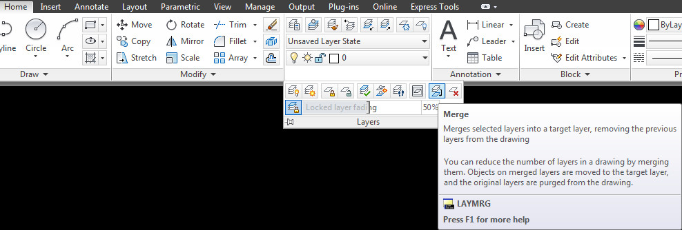
However I discovered two commands that would not require LISP or lots of work! If you don’t want the layer LAYDEL should do the trick but the one that was really awesome was LAYMRG. This merged the two layers and purged out the unused one and kept all the blocks intact!

This can be found on the ribbon in the following location:

Ribbonpositionlaymrg

Layer Merge (LAYMRG) icon location

Constrained

One of colleagues today noted that today he had annoying boxes. When I looked at his screen he had something like this.

Strange Boxes
Strange Boxes

These strange annoying boxes are constraints, part of AutoCAD’s parametric system, found under the Parametric Tab on the ribbon (strangely).

In order to use constraints you need to click the INFER constraints button on the bottom left of the status bar. This allows objects drawn in this mode to have the Parametric constraints. This button looks like this

Turn on Constraints
Turn on Constraints

Or this, depending on whether you use icons or not.

constraints01Once on you can draw your objects to be constrained. Here I have drawn a rectangle and a polyline. If I move the polyline the rectangle will deform as the polyline and the rectangle are linked or constrained together.

constraints04

constraints05

If you do not want this constrain feature on this object anymore you can click on the object and then delete constraints on the ribbon.

constraints06

Once removed the object returns to a plain old rectangle polyline.

constraints07

Remember to turn off the INFER constraints button before drawing anything else as all items drawn will have this parametric capability.


Cursor Trouble

So you got a nice shiny new machine, an AutoDesk certified graphics card and you’ve just installed the latest version of AutoCAD. All is great, you have lots of new features to help you productivity and you are steaming along. Then you insert an image and this image has a white background. Then your world falls apart. You can no longer see your cross hairs.

You have white cross hairs on a white background.

Don’t worry this problem can be sorted by turning off 3D acceleration. For some unknown reason AutoCAD does not have dynamic cursor colour when 3D acceleration is on!

Type 3DCONFIG in the command line, click “Manual Tune” and uncheck “Enable Hardware Acceleration”. The dynamic cursor colour now works.

Once you have undertaken the task needing the dynamic cursor colour feature you will probably want turn the acceleration back on.

3dconfig box

Paperspace Dimensions

One of my colleagues asked today, how do I get those paper-space dimensions to work?  As I tend to dimension in Model space (I need to research associative dimensions) on differing layers per style I never see the need to use paperspace dimensions.

So after a quick perusal of the Dimension style box, there is a check box to make the style to scale to paperspace. Cunningly called “Scale dimensions to layout”!

Dimension check box for paper space.

However strangely this did not work. After further searching I found that if the paperspace dimension is different when snapped to differing scale viewports then the DIMASSOC variable is most likely to be set to 1. Set it to 2. Then all will be good.