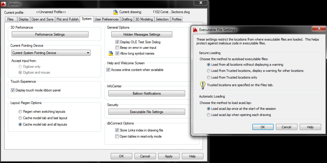
If you, like me, use LISPS you will find that a new very useful feature has been added to AutoCAD 2014. They have introduced Secure Loading of executables, which in principle is a good thing.
However if you like me are struggling to get the Trusted Locations to work, you can go back to the “legacy” behaviour (load everything anyway) by going to settings –> system –> executable file settings and turning off this feature.
As previously mentioned we updated the drivers to the latest ATI drivers for the Firepro and that seemed to stop the flickering. It however came back today. A restart of AutoCAD stopped it from flickering which is better than before as it was all the time.
On this forum post it has been suggested that network file access might be the issue. However its early days in troubleshooting!
One of my colleagues was asking, why can I not turn the frame off around this imported image? IMAGEFRAME was not turning the frame off. It turns out that the drag-and-dropped image was actually a PDF, and therefore the frame is controlled by PDFFRAME, so its worth noting the imported image type in order to control things like this.
However, it should be noted that all “frame” commands (IMAGEFRAME, PDFFRAME etc. can now be controlled by one single command FRAME. This appears to be valid from version 2012 onwards.
——
Excerpt from help, AutoCAD 2013 (c) AutoDesk.
Changing the setting for FRAME changes the IMAGEFRAME, DWFFRAME, PDFFRAME, DGNFRAME, XCLIPFRAME, POINTCLOUDCLIPFRAME, and WIPEOUTFRAME settings to the same setting as the new FRAME setting.
0 – The frame is not visible and it is not plotted. (The frame temporarily reappears during selection preview or object selection.)
1 – Displays and plots the frame.
2 – Displays but does not plot the frame.
3 – The settings vary for all objects with frames in the current drawing: images, underlays, clipped xrefs, clipped point clouds, and wipeout objects do not all have the same frame settings.
A colleague of mine had dropped in some blocks from an external source and found that they had two layers and wanted only one. They wanted to move all objects on one layer to another within the blocks.
Normally I would go about this, if there were no blocks involved, by using QSELECT. Then select the desired layer in the Ribbon and PURGE out the unused layer.
However as they are in blocks this does not work as the selection ignores the lines in blocks and just selects the blocks themselves. As we were after only specific lines in these blocks I was faced with exploding them all or some clever LISP.
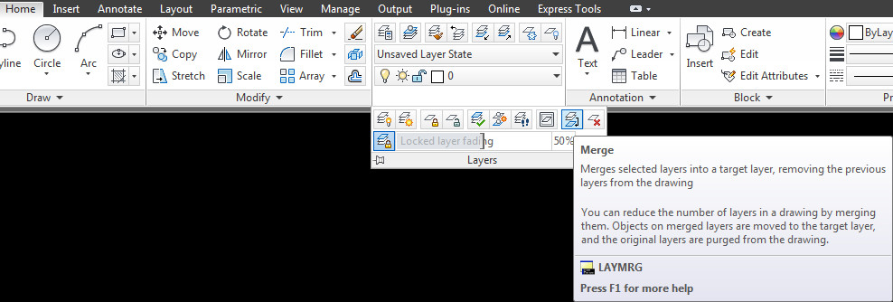
However I discovered two commands that would not require LISP or lots of work! If you don’t want the layer LAYDEL should do the trick but the one that was really awesome was LAYMRG. This merged the two layers and purged out the unused one and kept all the blocks intact!
This can be found on the ribbon in the following location:
I discovered today that some code can be typed straight into the command line in AutoCAD. I had not realised this, I thought all code had to be loaded as a routine.
The following changes the PSLTSCALE for all layouts!
I received a set of drawings today from a colleague, whilst this is not unusual, the drawings all had differing UCS settings, which was unusual, most of my colleagues do not touch the UCS.
Usually I reset the UCS to world and carry on. I like my modelspace to to be set to world so when I copy and paste the rotation stays the same to the screen. I tend to then rotate the UCS in viewports as and when required.
This time, typing UCS, W to reset to world UCS left me with this, a wonky UCS.
Wonky UCS
The UCS is wonky, or Y is not up the page. The square in the UCS indicates it is set to WORLD, so I was confused.
The problem was not that the view was set to the UCS but the UCS was (kind of) set to the view. I will explain. (See bottom of post for a quick explanation).
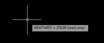
If you type VIEWTWIST, it should be set to 0 for the UCS to be the way I wanted it. I found it was set to 270!
Now I have run into another problem, the VIEWTWIST variable is readonly!
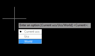
So lastly I found that typing PLAN and setting to WORLD reset everything to how I wanted.
For a quick method of the above, if the UCS is not in the default position and it is set to world, then the view has been rotated. To rotate the view back, type PLAN, then WORLD. Or click on the arrows above viewcube in full AutoCAD.
One of colleagues today noted that today he had annoying boxes. When I looked at his screen he had something like this.
Strange Boxes
These strange annoying boxes are constraints, part of AutoCAD’s parametric system, found under the Parametric Tab on the ribbon (strangely).
—
In order to use constraints you need to click the INFER constraints button on the bottom left of the status bar. This allows objects drawn in this mode to have the Parametric constraints. This button looks like this
Turn on Constraints
Or this, depending on whether you use icons or not.
Once on you can draw your objects to be constrained. Here I have drawn a rectangle and a polyline. If I move the polyline the rectangle will deform as the polyline and the rectangle are linked or constrained together.
If you do not want this constrain feature on this object anymore you can click on the object and then delete constraints on the ribbon.
Once removed the object returns to a plain old rectangle polyline.
Remember to turn off the INFER constraints button before drawing anything else as all items drawn will have this parametric capability.
One of my colleagues had put a point in a block to stop it from “growing in size”. Whilst this is an ingenious work-around, it is easier to control the size of points if you don’t want them to be massive when zoomed out in a drawing.
If you type DDPTYPE into the command line you will get this dialogue box.
DDPTYPE Dialog
The circle with a cross is my usual selection for style, the point size can be relative to the screen, where 5% is usually about right, or for my colleague’s requirements, absolute. This is in the base units for the drawing, e.g. MM or INCHES.
Note that you can set POINTS to be tiny dots and therefore nearly impossible to see and these do not scale at all. This is useful as sometimes a drawing can be full of points that are “invisible”.
So, you want to draw revclouds and you draw one in one drawing and move to the next drawing and discover the arc length has changed. Why does revcloud arc length change across drawings you wonder?
Let me explain why they change.
The revcloud command arc length is a global value and stays set across all drawings. So why then does it change? It changes as this value is not as static as it should be as the arc length value is a multiple of the current dimension style.
What, you ask is the point of this? I have no idea. Help suggests that it is to keep consistency, I find it does the opposite. Maybe I am using it wrong?
For me this is annoying, especially if you like me put your revclouds on paperspace as paperspace is scaleless. Equally annoying is that this scaling also occurs with annotative dimension styles…
Whilst this is not really a solution at least it might help those who cannot fathom why their arc lengths in revclouds keep changing.
This website uses cookies to give you the most relevant experience by remembering your preferences and repeat visits. By clicking “Accept”, you consent to the use of ALL the cookies.
This website uses cookies to improve your experience while you navigate through the website. Out of these, the cookies that are categorized as necessary are stored on your browser as they are essential for the working of basic functionalities of the website. We also use third-party cookies that help us analyze and understand how you use this website. These cookies will be stored in your browser only with your consent. You also have the option to opt-out of these cookies. But opting out of some of these cookies may affect your browsing experience.
Necessary cookies are absolutely essential for the website to function properly. This category only includes cookies that ensures basic functionalities and security features of the website. These cookies do not store any personal information.
Any cookies that may not be particularly necessary for the website to function and is used specifically to collect user personal data via analytics, ads, other embedded contents are termed as non-necessary cookies. It is mandatory to procure user consent prior to running these cookies on your website.