
Dimension Tips

As always in AutoCAD there are numerous ways to do the same thing, mainly due to the way the program has matured over the years. Items that existed way back in R12 are still there in R19.1 (2014), even if they have been replaced with a “better” implementation. These legacy options can sometimes be useful and also if you are encountering a problem its likely that something has been drawn using an older method that in not compatible with newer options.

Dimension without any text added

Take for instance text suffices for dimensions. The usual way to append text is to either set it as default in the Dimension Style Editor or append it for an individual dimension using the properties box (see above).

However you can also append text using <> then whatever text in the Text Override box. This is useful as you can have this as well as a Prefix and a Suffix. The <> represents the dimension. For instance if I have a prefix of SO and a suffix of mm, I can use the following in the Text Override,

Overall <> opening

to achieve,

Overall SO 1045mm opening

This can be useful for one off dimensions where the text needs to be padded out to make the dimension clearer and the dimension style is carrying suffices that are required to be kept.

Dimension with text suffix option 2
Dimension with text suffix

The override box can also be used to place text below the dimension line whilst the dimension remains above. This is done using the <> X modifier! For example;

<> XTEXT

Dimension with text below the dimension line

Note that if you want the text to be centred no space is required between “X” and the text required otherwise a space precedes the text below the line.

The major drawback with using text override as the main method for applying suffices is that Match Properties will not carry the text override from one dimension to another, it has to be retyped, whereas a dimension with Suffix used will carry over.

Match Properties Settings

A quick post to highlight that AutoCAD has a lot a “hidden” settings that most people (including me) don’t use or even know about.

Take for instance Match Properties, this actually has a selective settings box so that only some of the properties from the source object are matched!

Match Properties Dialog Box

Note that when Match Properties is clicked and the source object is selected AutoCAD lists the current settings under “Current Active Settings”, usually this is everything, however you can type S (or click settings in 2013 and above) and you will be presented with the dialog to turn off (or on) various properties to copy.

XREFs and Layers

A colleague of mine was struggling with numerous issues when using XREFs. The two main ones where having multiple Layer States with XREF prefixes that couldn’t be removed and the other was not wanting to see the XREF layers.

Layer States Dialogue for no XREFs does not work with Ribbon pulldown

The first issue was frustrating as whilst there is an option to disable these is in the layer states manger dialogue, checking the box does not disable them in the Ribbon pulldown. Duh. So the solution ended up being, delete the layer states in the XREF.

The second issue was easy to solve as AutoCAD has this feature built-in and it works! It works with both the Layer Pulldown, Layer Palette and Classic Layer! Wow!

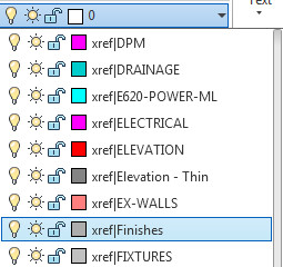
Layer Drop Down showing XREF layers

This is how to remove XREF layers from these palettes. You will need a filter (yup AutoCAD has layer filters!)

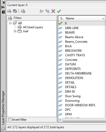
Layer Pallette indicating the filter section
Layer Palette indicating the filter section

On the panel on the left, click XREF, this will now show the list of layers for the XREF. Click on the checkbox below that states Invert Filter and voila, you have a list of layers without XREF layers within.

Rotate Viewport

One of my colleagues was asking how do I rotate a view in a specific viewport. I was all over this, and was like there are several ways, however the way I use is to use UCSFOLLOW, then rotate the UCS, turn off UCSFOLLOW and voila view rotated in viewport that is different to that of the model space.

Another colleague was like why don’t you rotate the viewport itself, that would be easier?

I was like, viewports don’t rotate? He rotated the viewport and wow! The view inside followed. This works for any angle!

The system variable that controls this is VPROTATEASSOC which has been in AutoCAD since 2010!

Rotate Angle for Manual Rotate

One of my colleagues just asked, where is the dynamic feedback for the rotate angle when using rotate.

I played with the setting for a bit and discovered that angular information is not available during rotate! How dumb is that?

There is a work-around though. Go to Drafting Settings (right click on OSNAP, OTRACK etc, they all bring up the same dialogue, just on a different tab) then go to POLAR TRACKING and set the Increment Angle to 1 and the Polar Angle measurement to last segment.

Polar tracking option for 360 degree angle feeback
Polar tracking option for 360 degree angle feedback

Now when rotating you will see 360 degree information, useful for rough rotates by eye.

Remember to change these back after your rotate command! Thinking about it, it is probably possible to turn this into a script and button so that you have a “Rough Rotate” command.


Flickering Update Again

Further to my previous post regarding renaming AecCore.crx, it has been suggested that this could break other things. A slightly “better” patch would be to copy the AecCore.crx from the 2013 install and place it into the 2014 folder. This does work and no visible breakage yet!

Our CAD support people have suggested that this patch is a reasonable temporary solution though they say if an update from AutoDesk arrives then you will need to revert back to the 2014 version of the AecCore.crx file before installing the update.

Also the CAD support people looking at this flickering issue with AutoDesk at the moment and I will let you know the outcome of that.

Another flickering update

It appears that changing AecCore.crx in C:Program FilesAutodeskAutoCAD LT 2014 to AecCore.crx.old or similar (in order to stop it working) fixes the flickering symptoms, making the program usable again. However this will most likely break something else as this file is an object enabler. The underlying issue appears to be with the new mapping feature (which makes sense as there is a greyed out map pin next to unrecognised when the bar flickers) and that is not working properly.

We all wait now for a Service Pack or Hot Fix for this from AutoDesk. Please check out this page regularly to see if the hot fix or service has been posted. I will update my blog when it arrives to see if it fixes the issue!