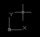
One of my colleagues had a drawing where the UCS had been rotated to suit a particular part of the drawing, however on setting the UCS back to World the World UCS was also rotated. AutoCAD helpfully shows the cursor as skewed if the UCS icon is not visible or obvious.
The UCS icon when rotatedThe World UCS rotated
This is due to the Plan view not being updated to suit the World UCS and is the exactly the same problem as noted in my UCS World post. Just type PLAN and select World to get back to normal. You can always tell if you are in World view by the UCS icon having a little sqaure on it. Any other view will just show the two axes.
The World UCS as seen normally
As this is now really an LT problem as the full version of AutoCAD has a nifty rotate view button I have written a couple of scripts to set the UCS to an object and then rotate both the Plan and UCS to suit that object and also a useful one to get back to a World view. These will be published shortly as part of my customising AutoCAD series.
One of my colleagues found that qleader heads (not the lines but just the heads) would plot in a viewport even when turned off. This seems to only affect DWG to PDF plots but might affect other plotters.
The solution to the problem is to freeze off the layer with the qleader on rather than just turning off, this way the object is completely off and won’t show though even if its not supposed to!
One of my colleagues was wanting dimensions that show a half (.5) after the measurement for when setting out brick diemsnions but not wanting the dimenions to have point something (e.g. 0.34 or .0) after them. And another wanted km dimensions. I will explain how to do both of these here.
Trailing Zeros
So lets alter the new dimstyle created in that post, called Adams – 1_100.
If we go to the primary units section, change the precision to 0.0 and the round off to 0.5, this will allow the dimension to only present halves of numbers and not other fractions. All dimensions will now look like this: 1000.0 or 1020.5.
In order to remove the .0 for dimensions that do not require it, check the trailing zero supression box and now dimensions will look like this: 1000 or 1020.5.
km from mm
For example if you draw in mm and want to present the dimensions in km, again go to the primary units tab and add km as a suffix and change the scaling to 0.000001. This is the conversion factor from mm to km. Now the dimensions will only display km. As the precision is not required at that scale I would change the precision to 0.0 and add zero supression.
I would suggest creating a new dimension style when altering the dimension this drastically.
So once you have created you default text style (NOT STANDARD), click on the annotation panel again and go to the dimension style editor.
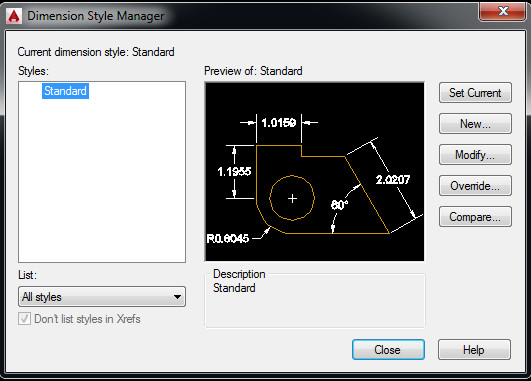
Default dimension style
You will get a similar box to the text style dialog, albeit the preview has moved from bottom left to the centre! However the principals are the same. Again, please do not use standard.
So, click on the new and you will get a box, give the dimension a name. Again, similar to the text style, give it a name that reflects where it came from and what it does, e.g. ‘company name – 1:100’ (metric), or ‘company name – 1/8″=1’-0″ ‘ for imperial.
Create new dimension style
You should note that AutoDesk being totally dumb have excluded pretty much every symbol that describes an imperial or metric scale. So the above two examples have to be re-written to make sense but won’t actually follow standard notation.
– company name – 1_100 (metric)
– company name – 1_8_-_1-0 (imperial)
Unsupported Characters
Again, this is only a suggestion of how to put it together, just keep it simple to allow others to get what the style is to be used for!
I am going to use metric for this example, however the principals will be the same for imperial.
So once you have entered the name, you will be presented with the (rather complex) dimension style editor box. This is a very powerful set of rules that can present dimensions however you want, some of the features are:
– rounding of dimensions
– scaling to other units, e.g. if you draw in mm, the dimstyle can display km!
– zero supression at both end and beginning
– location of text
– style of leaders
– style of lines and more!
The first tab to the left is lines, we will come back to that one. First lets set up the text.
Text
Text tab, dimension style
Change the text to the text style you created, this hopefully won’t grey out the text height in the dimension style. If you altered the text style height to anything other than 0, you caa change the height in this box, I usually use 2.
I like my dimension text to be centred and aligned to the dimension line.
When looking at the numbers on all the the tabs, they will be point something. This is because the defaults are set up for imperial. If in doubt change these to 1 for metric. Sometimes a 0.5 or 2 might be more suitable. A little playing with the numbers after creation will get the dimension style looking as you want it.
Lines
Line tab, dimension style
After the text is setup, lets look at lines. The default for this page is everything set by block. If you, like I, draw using layers, then change all “ByBlock” to “ByLayer”.
I also like to make my lines a little fancy by changing the extension lines to a grey (that plots light in colour) and to “hidden” to provide an unintrusive dashed line back to the origin points.
Don’t forget to change the spacings to 1.
Symbols and arrows
Symbols and arrows tab
Most of the settings on this page are personal preference. I prefer architectural ticks on my dimensions and a little arrow on my leaders.
I found from experince that 1.5 for arrow size seems to work quite well, center marks at 1 and a break size of 2.
Fit
Fit Tab
This one is where the overall scale (if not annotative) is set. Once one dimension style is set up, it can be copied at the “use overall scale” section changed to suit the scale. e.g. here we are going to change the overall scale to 100 for a 1:100 dimension style. If 1:50 change this to 50.
The rest of the options in this section I leave at default.
You will notice that once the overall scale is changed the preview might go wild. If it does, just close and click your style and click modify.
Primary Units
Primary units tab
This is where the precision and rounding is undertaken for the dimension style. You can also add suffix to the dimension.
Here I have altered the precision to 0.0 and changed the round off to 0.5 as precision greater than this is not normally required at 1:100. In fact you could change the precision to 0 and round off to 1 or even 5. Round off takes the dimension of say 3549.23435 (if measured using DISTANCE) and displays a more friendly number in the dimension. So if the round off was 5 and the precision 0, the dimension would read 3550.
Alternate Units and Tolerances
These are not generally used in architecture and for this tutorial the defaults will be left on these two tabs.
As a small note in association with my another post of mine on trailing zero dimensions, I thought it would be handy to suggest how to set up a new text style.
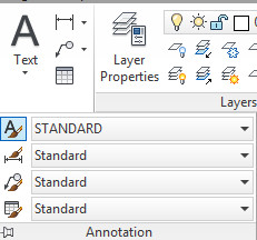
If you go to the Annotation panel under the Home tab on the Ribbon and click on the drop down you will get a list of current styles for text, dimensions etc. Click on the text style button and you will get the text style dialog box. This can also be found under the format menu or by typing STYLE.
Text style ribbon location
You will be presented with a STANDARD style in the box. PLEASE DO NOT EDIT THE STANDARD STYLE! I cannot emphasise this enough. If you copy and paste from one drawing to another where someone has edited the standard style, everything pasted will change, this includes dimenions based on the style etc. Just don’t do it!
Text style dialog box
So now, lets create a new style. I am going to call it Adams – Standard. Very orginal, but this should be descriptive or where it came from. Company name followed by a hypen and then sub-categories is a good way to go. E.g. ‘Adams – Standard’, ‘Adams – Dimensions’ (if different) or ‘Adams – title text’ are good places to start. For now everything will be based on one style to keep it simple.
Once you have clicked New, then entered the name, now we can change the settings. These are the defauly settings for the style. I am going to use Arial and leave it at normal.
Other settings include height, whether it is annotative (paper space height) or what angle it is at.
Most should be left alone:
– Height should be set to 0 if you are going to be using this style with a dimension style.
– Width factor should be set to 1, unless you want to have stretched out text (note this is not kerning but is just stretching the text).
In order to create custom commands and then assign them to a button in AutoCAD you will need to create a MACRO. This is so for all buttons, even those that call a LISP or OBJECTARX piece of code.
The MACRO is basically a list of the inputs on the command line listed out in one line.
A simple MACRO would look like this:
^C^Cplot;
This if turned placed in a button would bring up the plot dialog box.
The ^C^C is the code for pressing “escape” twice. This clears any active commands in case one is running.
The ; is the representation of enter. Any number of commands can be strung together into one MACRO.
MACROs also allow for input for selecting objects and this is written with a space and then a backslash.
I will be running through several of my custom commands to show how they are put together.
Customising AutoCAD can be quite daunting so I thought I would produce a few posts to run through the process of customisation from creating a new Ribbon tab and ribbon panels from scratch through to adding your own buttons.
Button creation is probably the most important as they can contain scripts to optimise and speed up many tasks.
These posts will be within the Customisation Category.
In my previous post, I mentioned that you could go back to the more traditional start up in AutoCAD by changing the STARTUP variable to 0. This does not however remove the New Tab if you close all drawings, in order to go to a blank AutoCAD when all drawings are closed, change NEWTABMODE to 0.
Having now noticed that the shortcut entry in the start menu for AutoCAD LT 2015 is broken on several machines I have used, I would go as far as saying this is probably a common issue, however I cannot seem to find much on the internet about it.
The issue is when you click on “AutoCAD LT 2015 – English” under the AutoDesk – AutoCAD LT 2015 – English folder, AutoCAD attempts to configure itself again, even though it is installed and configured. After a short space of time the configuration will fail resulting in a pop-up stating
“Run setup.exe to install AutoCAD LT 2015 – English”
Clicking on the OK button results in another pop-up stating
“Fatal error during installation.”
Not particularly helpful AutoDesk, did you actually test this software? Useless software support as usual. Anyway, as the desktop shortcut works fine (I hope you didn’t delete it), all you need to do is delete the broken shortcut in the start menu and copy the desktop shortcut into the folder.
To do this, left click on the Windows Blob and then right click on “All Programs” and go to “Open All Users” (under a locked down environment this will need Administrator rights to edit).
Double click on Programs and again on Autodesk and then once more on AutoCAD LT 2015 – English, now you will see a Migrate Custom Settings Folder, Attach Digital Signatures link and the AutoCAD LT 2015 – English link. Delete this link and copy the one from the desktop to this folder. Close window and the Start menu will now have a working link.
This website uses cookies to give you the most relevant experience by remembering your preferences and repeat visits. By clicking “Accept”, you consent to the use of ALL the cookies.
This website uses cookies to improve your experience while you navigate through the website. Out of these, the cookies that are categorized as necessary are stored on your browser as they are essential for the working of basic functionalities of the website. We also use third-party cookies that help us analyze and understand how you use this website. These cookies will be stored in your browser only with your consent. You also have the option to opt-out of these cookies. But opting out of some of these cookies may affect your browsing experience.
Necessary cookies are absolutely essential for the website to function properly. This category only includes cookies that ensures basic functionalities and security features of the website. These cookies do not store any personal information.
Any cookies that may not be particularly necessary for the website to function and is used specifically to collect user personal data via analytics, ads, other embedded contents are termed as non-necessary cookies. It is mandatory to procure user consent prior to running these cookies on your website.