The viewport itself is on an off layer. This will show the content but no boundary so the viewport cannot be selected and moved etc. Check whether the viewport layer is off by turnign all layers on and unfreezing all layers. This should then reveal the boundary.
The viewport has been put on Defpoints, which when combined with Layer 0 being off will display the viewport boundary but it will be unselectable. This is why Defpoints should not be used for any user geometry.
Lastly and this is what I encountered today which is the first time for me is that someone has clipped the viewport and then deleted the clipping boundary. This gives a viewport that is completely unselectable by the mouse. However it can be selected using Quickselect, see below for the method to remove this viewport.
Unclipping a clipped viewport that has had its boundary delelted!
Firstly we need to create a rectangle, this is needed for a later step.
Then run Quickselect (its on the “Home” tab under the “Utilities” group),
Quick select location
and then select “Viewports” from the dropdown box at the top. Then go to the bottom box and select “Select All”.
Quick select all viewports
Once all the Viewports are selected and if there are other viewports you want to keep, use the shift key to de-select the ones that have borders leaving only the one that has no boundary.
Then go to the layout tab and select “Clip”, and select the rectangle you created at step one. This will clip the old viewport to the rectangle.
Viewport clip
You can now either delete the viewport and rectangle or move and edit the viewport as required.
I would however suggest deleting the viewport and rectangle as this issue could happen again and create a new viewport using the layout tab new rectangular viewport option.
If you use a system of drawing sheet and drawing model in your practice where both are seperate files and the sheets are like a piece of paper with the drawing information pulled into it then this is something you might have come across already, if not then this might help you in the future if you encounter it.
So generally you will attach one or two external drawings to a sheet file and then adjust layers to suit in the sheet file. However occaisonally you will set up a drawing with an XREF, usually an overlay type of drawing (not to be confused with overlay type of XREF) where you have a base drawing and the layers are adjusted to be simplistic and then further information is drawn over the top, e.g. a fire drawing or drainage drawing.
This is where it gets complicated. There is now a chain of drawings. Drawing A (the base drawing) –> Drawing B (the overlay type of drawing) –> Drawing C (the plot drawing). [Note: the arrows indicate XREF attachements]. This chain of XREFs is called nesting.
The problem comes when you want Drawing C to look the same as drawing B does. When you attach Drawing B to C all the layers on drawing A change to when they were first attached to drawing B, all the changes in drawing B seem to be lost. But when you go back to drawing B it still looks as it should. Confused?
The problem is AutoCAD pulls in XREFs (external references) from their source files and not through the nesting. So any information for drawing A setup in drawing B will not be imported into C as drawing C as the information is directly pulled from drawing A.
In order to circumvent this annoying behaviour layer states export and load should be used. Or you just reset them up if its only a few changes, but if lots of colour changes and layer adjustments have been made then this is the method for you.
This is taken from this page: (Copyright AutoDesk).
To export layer settings
At the command prompt, enter LAYER.
In the Layer Properties Manager, click Layer States Manager.
In the Layer States Manager, create a new layer state or select an existing one. Click Export.
In the Export Layer State dialog box, enter a file name and specify a location for the file.
Click Save.
Click OK to close each dialog box.
To restore layer settings
At the command prompt, enter Layer on the command line.
In the Layer Properties Manager, click Layer States Manager.
In the Layer States Manager, select a named layer state.
Select the settings that you want to restore.
Click Restore.
Click OK
Now you should have the correct layer information in drawing C!
One of my colleagues noted that she wanted all her measurements to be in imperial when dimensioning for her client. The drawing had been drawn in metric mm.
Whilst there are ways to convert the drawing in its entirety into imperial and visa versa, there is very little information on temporarily change the units or dimension style.
So here is how to place an imperial dimension on a metric drawing.
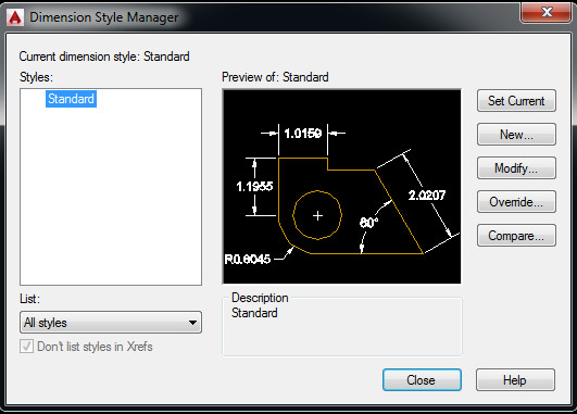
First go to the dimension style manager (_DIMSTYLE) and then select your dimension that you will be starting with. In our office we have a dimension style for each scale the drawing will be printed at (we have not got to annotative objects yet…). So I started with 1:100.
Metric Dimstyle, Primary Units tab
Click on new and it will create a new style based on the 1:100 dimension style selected. I renamed the new style to 1:100 feet so its clear that it is a different style but has the scale of 1:100 and is in feet!
Then leave every other setting alone and go to the Primary Units section. Change the unit format to Architectural and the Precision to 0′-0″.
Then change the scale factor to 0.0393700787. This scales the mm in inches. It is the basically the conversion of 1mm to 1inch.
Imperial Dimension (for metric drawing), Primary Units tab
Save style and that’s it. You now have a dimension style that outputs feet and inches from a metric drawing. Even better you can have both metric dimensions and imperial on the same drawing with this method.
My colleague asks me today, “why are my dimensions hollow and not filled?” I thought, maybe FILLMODE is not set. But that was OK.
It turns out that this can be caused by non-flat or “elevated” drawings. I.e. 2D drawings that extend into 3D space. Usually caused by UCS not being rotated properly and it being skewed into 3D space.
The solution is to change the UCS in the modelspace or paperspace viewport so it is flat and things should be back to normal!
If you have decided to place all AutoCAD items in a central location and link each machine across the network to those locations by adding them to the “Support File Search Path” then this is for you!
I was experiencing really slow mtext editing, slow loading of options dialog and slow loading of the hatch editor. I did some digging and found very few solutions. Only one that caught my eye where the response was “Maybe that’s part of the problem. ” I thought, lets test that. I removed the network paths from the support path and voila! Everything is blisteringly fast again.
In my next post on customisation I will be looking at more advanced macro writing. After this post there will be a few individual macro examples which should be helpful!
In this tutorial I am going to refer to two UCS commands I have written to get around the lack of easy plan rotation in AutoCAD LT. In full AutoCAD you get a rotation box in the upper right corner that looks like the one below. This is unfortunately not available in LT.
Rotate from Viewcube
These are a bit more automated version of the tutorial I have posted before as I decided that even that was too much effort!
—–
The first macro rotates the UCS back to world and takes the plan view with it. This avoids the need for UCS follow being set to 1 and the annoying zoom extents bug it has.
^C^Cucs;w;plan;w;
So lets break down the macro above. Its just a simple chain of commands to do with the UCS and PLAN.
The first ^C^C at the beginning is escape twice to ensure that the command line is clear
Then the UCS command is started
Then the UCS command is told to reset to (W)orld
Then the PLAN command is started
Then the PLAN command is told to reset to (W)orld
Now the drawing is viewed in world view and the UCS is orientated the same way.
——
The second macro rotates the UCS to an object and then updates the view to suit.
^C^Cucs;ob \plan;c;
So lets break this one down as it has something slightly different in its layout.
The first ^C^C at the beginning is escape twice to ensure that the command line is clear
Then the PLAN command is told to update to the (C)urrent
——
This formula can be used to make further buttons to emulate the plan rotate found in full AutoCAD or make any chain of commands work.
A quick way to create a macro is to run a command and follow the command line and write down your inputs and once you have completed the command you have the basics for putting together a macro.
—–
Lets make a macro to rotate the UCS and PLAN to the right. Here is a copy of the command line and below that is a list of the command inputs and then the resultant macro.
Command line:
Command: UCS
Current ucs name: *NO NAME*
Specify origin of UCS or [Face/NAmed/OBject/Previous/View/World/X/Y/Z/ZAxis] <World>: z
Specify rotation angle about Z axis <90.00>: 90
Command: PLAN
Enter an option [Current ucs/Ucs/World] <Current>: c
Regenerating model.
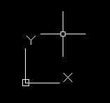
One of my colleagues had a drawing where the UCS had been rotated to suit a particular part of the drawing, however on setting the UCS back to World the World UCS was also rotated. AutoCAD helpfully shows the cursor as skewed if the UCS icon is not visible or obvious.
The UCS icon when rotated
The World UCS rotated
This is due to the Plan view not being updated to suit the World UCS and is the exactly the same problem as noted in my UCS World post. Just type PLAN and select World to get back to normal. You can always tell if you are in World view by the UCS icon having a little sqaure on it. Any other view will just show the two axes.
The World UCS as seen normally
As this is now really an LT problem as the full version of AutoCAD has a nifty rotate view button I have written a couple of scripts to set the UCS to an object and then rotate both the Plan and UCS to suit that object and also a useful one to get back to a World view. These will be published shortly as part of my customising AutoCAD series.
One of my colleagues found that qleader heads (not the lines but just the heads) would plot in a viewport even when turned off. This seems to only affect DWG to PDF plots but might affect other plotters.
The solution to the problem is to freeze off the layer with the qleader on rather than just turning off, this way the object is completely off and won’t show though even if its not supposed to!
One of my colleagues was wanting dimensions that show a half (.5) after the measurement for when setting out brick diemsnions but not wanting the dimenions to have point something (e.g. 0.34 or .0) after them. And another wanted km dimensions. I will explain how to do both of these here.
Trailing Zeros
So lets alter the new dimstyle created in that post, called Adams – 1_100.
If we go to the primary units section, change the precision to 0.0 and the round off to 0.5, this will allow the dimension to only present halves of numbers and not other fractions. All dimensions will now look like this: 1000.0 or 1020.5.
In order to remove the .0 for dimensions that do not require it, check the trailing zero supression box and now dimensions will look like this: 1000 or 1020.5.
km from mm
For example if you draw in mm and want to present the dimensions in km, again go to the primary units tab and add km as a suffix and change the scaling to 0.000001. This is the conversion factor from mm to km. Now the dimensions will only display km. As the precision is not required at that scale I would change the precision to 0.0 and add zero supression.
I would suggest creating a new dimension style when altering the dimension this drastically.
So once you have created you default text style (NOT STANDARD), click on the annotation panel again and go to the dimension style editor.
Default dimension style
You will get a similar box to the text style dialog, albeit the preview has moved from bottom left to the centre! However the principals are the same. Again, please do not use standard.
So, click on the new and you will get a box, give the dimension a name. Again, similar to the text style, give it a name that reflects where it came from and what it does, e.g. ‘company name – 1:100’ (metric), or ‘company name – 1/8″=1’-0″ ‘ for imperial.
Create new dimension style
You should note that AutoDesk being totally dumb have excluded pretty much every symbol that describes an imperial or metric scale. So the above two examples have to be re-written to make sense but won’t actually follow standard notation.
– company name – 1_100 (metric)
– company name – 1_8_-_1-0 (imperial)
Unsupported Characters
Again, this is only a suggestion of how to put it together, just keep it simple to allow others to get what the style is to be used for!
I am going to use metric for this example, however the principals will be the same for imperial.
So once you have entered the name, you will be presented with the (rather complex) dimension style editor box. This is a very powerful set of rules that can present dimensions however you want, some of the features are:
– rounding of dimensions
– scaling to other units, e.g. if you draw in mm, the dimstyle can display km!
– zero supression at both end and beginning
– location of text
– style of leaders
– style of lines and more!
The first tab to the left is lines, we will come back to that one. First lets set up the text.
Text
Text tab, dimension style
Change the text to the text style you created, this hopefully won’t grey out the text height in the dimension style. If you altered the text style height to anything other than 0, you caa change the height in this box, I usually use 2.
I like my dimension text to be centred and aligned to the dimension line.
When looking at the numbers on all the the tabs, they will be point something. This is because the defaults are set up for imperial. If in doubt change these to 1 for metric. Sometimes a 0.5 or 2 might be more suitable. A little playing with the numbers after creation will get the dimension style looking as you want it.
Lines
Line tab, dimension style
After the text is setup, lets look at lines. The default for this page is everything set by block. If you, like I, draw using layers, then change all “ByBlock” to “ByLayer”.
I also like to make my lines a little fancy by changing the extension lines to a grey (that plots light in colour) and to “hidden” to provide an unintrusive dashed line back to the origin points.
Don’t forget to change the spacings to 1.
Symbols and arrows
Symbols and arrows tab
Most of the settings on this page are personal preference. I prefer architectural ticks on my dimensions and a little arrow on my leaders.
I found from experince that 1.5 for arrow size seems to work quite well, center marks at 1 and a break size of 2.
Fit
Fit Tab
This one is where the overall scale (if not annotative) is set. Once one dimension style is set up, it can be copied at the “use overall scale” section changed to suit the scale. e.g. here we are going to change the overall scale to 100 for a 1:100 dimension style. If 1:50 change this to 50.
The rest of the options in this section I leave at default.
You will notice that once the overall scale is changed the preview might go wild. If it does, just close and click your style and click modify.
Primary Units
Primary units tab
This is where the precision and rounding is undertaken for the dimension style. You can also add suffix to the dimension.
Here I have altered the precision to 0.0 and changed the round off to 0.5 as precision greater than this is not normally required at 1:100. In fact you could change the precision to 0 and round off to 1 or even 5. Round off takes the dimension of say 3549.23435 (if measured using DISTANCE) and displays a more friendly number in the dimension. So if the round off was 5 and the precision 0, the dimension would read 3550.
Alternate Units and Tolerances
These are not generally used in architecture and for this tutorial the defaults will be left on these two tabs.
This website uses cookies to give you the most relevant experience by remembering your preferences and repeat visits. By clicking “Accept”, you consent to the use of ALL the cookies.
This website uses cookies to improve your experience while you navigate through the website. Out of these, the cookies that are categorized as necessary are stored on your browser as they are essential for the working of basic functionalities of the website. We also use third-party cookies that help us analyze and understand how you use this website. These cookies will be stored in your browser only with your consent. You also have the option to opt-out of these cookies. But opting out of some of these cookies may affect your browsing experience.
Necessary cookies are absolutely essential for the website to function properly. This category only includes cookies that ensures basic functionalities and security features of the website. These cookies do not store any personal information.
Any cookies that may not be particularly necessary for the website to function and is used specifically to collect user personal data via analytics, ads, other embedded contents are termed as non-necessary cookies. It is mandatory to procure user consent prior to running these cookies on your website.